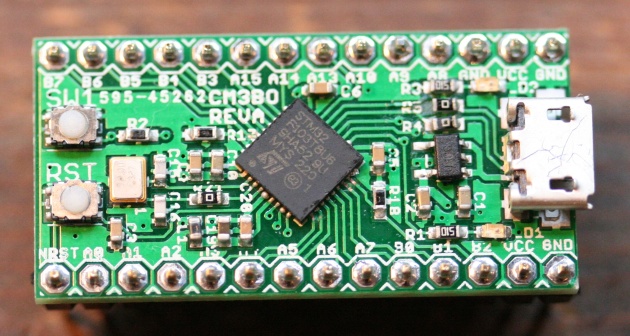
 When I prototype a simple design requiring a microcontroller on a boardboard, I often pop in an Atmel AVR in a DIP package. When I also need easy connectivity over USB to a host computer, I use the SparkFun Pro Micro, a simple DIP breakout board for the ATmega32U4. I like the form factor of the Pro Micro, but lately I’ve been moving away from the AVR in favor of the STM32. So I decided to design a simple DIP breakout board for a small member of the STM32 family. I chose to base the design on the STM32F103 in a 36-pin VFQFN package. The board features microUSB (the power source), a 300mA 3.3V Microchip voltage regulator in a SOT-223 package, two LEDs, a 12MHz crystal for the high-speed external clock, a reset button and one user-defined button. The LEDs and all passives are 0603. The entire board is 0.7in by 1.4in. I break out GND, VCC, NRST and all the IO pins, including those wired to the LEDs and push button. I used Hackvana to fab the design.
I’ve tested all the functionality of the board and it works as designed with one errata: I missed a pull-up resistor in the USB interface which I patched by hand (not pictured).
Soldering the VFQFN was a challenge. I made three boards and the first two had some bridging on the STM32 part after reflow which I was able to clean up with solder wick by hand.
I’m planning to respin the board with a few changes. In addition to fixing the USB problem, I’d like to move to the 48-pin UFQFN, make the board slightly longer to break out the additional IO, add an external crystal for the 32KHz RTC oscillator, and break out VIN so the board can be powered without USB. Any other suggestions?
If and when I’m happy with the updated board, I plan to release the design files and make some extra for sale.
Hello Cotton, happy to hear your boards arrived, and even happier to hear your boards work!
AVRs have been a hacker staple for many years, but the time of ARM is upon us. Convenient breakout boards like this are part of what’s going to bring that ARM power to everyone. Nice work!
I’d suggest just placing pads for a 32kHz tuning fork crystal and the caps on the bottom if there’s room. You don’t have to populate them, but those low power clock circuits are sensitive to layout.
You also might want to break out the V_bat pin if you want to use the RTC.
Thanks for the suggestions! I’m working on a new version of the board using the 48-pin QFP that can support members of the F1 and F3 family. I added a 32KHz oscillator (not available in the QFN package I used here). The board will be slightly longer (2″) to break out the additional I/O. I hadn’t thought to break out Vbat: great idea!
why is there a zero ohm resistor on one of the crystal pins?
why are the USB terminating resistors also zero ohm?
also on my STM32 projects, I find that adding a pull-up resistor actually causes problems, maybe the F1 series is different from F2 or F4 in that regard?
Hi Frank,
1. According to ST Micro Application Note AN2867, Oscillator design guide for ST microcontrollers, depending on the crystal, it can be necessary to have an external resistor to limit the drive level to prevent the oscillator from oscillating at an overtone. I didn’t need it in this case, but I put the resistor in so I could change it in the future.
2. I wasn’t completely sure about this, but the F1 datasheet didn’t show resistors in the USB circuits and the F1 reference boards either didn’t use resistors or use 0R. I think this might be a difference between plain FS USB and OTG or maybe is just a difference between F1 and F4.
3. The F1 docs clearly say a pull-up is required to be complaint with FS USB, and I found it wouldn’t work without it. I think the difference is FS USB vs OTG.